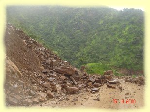
The
slopes which are susceptible to failure by various modes like, plane, wedge
or circular mode of failures can be stabilized by various methods. These
methods could be as simple as altering the geometry of the slope or comparatively
complicated and difficult like providing reinforcement and retaining structures.
The important factors which influence the stability of the slope are; i)
slope angle ii) dip of the failure plane or plunge of the line of intersection
of two wedge forming planes iii) shear strength parameters, cohesion and
angle of internal friction and finally the water saturation condition.
For the stability condition either of the above-mentioned factors may have comparatively high or low influence. Some of the factors may be responsible in inducing the forces for sliding where as, the others may contributes in providing the resistance to the sliding. The net result of these factors will defines whether the slope is going to slide, under the given conditions, or it will be stable. The relationship of the factors responsible for inducing sliding and the factors responsible to provide resistance to the sliding is defined by the limit equilibrium. Factor of safety can be defined as the ratio of the total forces available to resist sliding to the total forces available to induce sliding. If the factor of safety is less than unity, it implies that the resistive forces are less than that of the forces which induce sliding. Thus, for the condition when the FOS is less than 1.0 the slope may fail, provided it is subjected to a triggering factor, natural or man made. The factor of safety of a potential unstable slope may be improved by providing several methods such as, safe slope design by altering the geometry of the slope, reinforcement by providing rock bolts, retaining structures, shotcreating etc. Remedial Measures for Slope
Slope Design A considerable stability can be achieved by making concave slope face. The safe slope angles for a given slope can be obtained by adopting technique proposed by Hoek and Bray, 1989. In this technique, the factor of safety is obtained by assuming different slope angles and slope heights. The factor of safety, as calculated for each combination of slope angle and slope height, is marked over a graph sheet by taking slope angles on X-axis and height on Y-axis. Later, a contour curve corresponding to a factor of safety equal to 1.2 is drawn. Thus, the safe slope angles for different slope heights are obtained from this graph. Based on these safe slope angles a slope cross section is prepared in which height of the slope is considered from top to bottom. Rock Bolting Rock bolts are used to reinforce jointed rock much as reinforcing bars supply tensile resistance in reinforced concrete. In rock slope, tunneling and underground mining, steel rod inserted in a hole drilled in the face of a rock formation to support the sides or roof of the excavation.These are equally effective in natural and cut slopes, as these rock bolts act as a binding tools between the two rock blocks on the either sides of the discontinuity plane. The bolt may be provided with an expanding device to grip the rock at the far end of the hole or may be bonded to the rock by means of expanding cement. Rock bolts may be used singly or in rows.There are static and tensioned rock bolts. Tensioned rock bolts should be used only where a force is needed to counteract the forces making the structure unstable. |
In
most cases static bolts should be used. The logic behind a static bolt is
that if the structure is safe enough to drill into and install rock bolts,
it already has an inherent factor of safety. If the stability of the structure
is adversely affected in the future the static bolt will automatically go
into tension with the exact amount of force and in the exact location that
it should.
Improving Drainage of the slope When there is an influence of water saturation the slope section becomes unsatable for static and dynamic conditions. Therefore if somehow, the drainage is controlled the slope section may demonstrate stable condition. In order to improve the drainage conditions horizontal collection drain in the crest region on upper slope may be provided which may collect the rain water and drain it away from the slope face. In addition to this on the upper slope surface and on the slope face shotcreting with wire mesh and random Rock bolts, may also be provided. In addition to this it is suggested to provide perforations in between the shotcreting surface, so that the water if any trapped, in between the shot creating layer and the slope face, be drained out. Remedial Measures for Slope Section Having Rotational Mode of Failure In case of slopes which has a potential for rotational mode of failure demonstrates great challenges for the geotechnical engineers and engineering geologists. Such slopes which are mostly heterogeneous in nature, pose problems while estimating the shear strength properties for the material. The cohesion for soil mass under saturated conditions may approach zero value under such condition the slope will be unstable for all static and dynamic condition, though practically it would be very rare chance that cohesion becomes zero. For such slopes the most feasible remedial measure is to improve the slope geometry and to provide the proper drainage system. The retaining wall may be provided at the toe of slope with perforated weep holes, this may help in draining any excess water trapped in between the wall and the soil face, which may generate pore water pressure. In addition to this along the toe, just at the junction of the wall, a lined drain may also be provided. This will help in draining the water which may damage the foundation of the retaining wall. Reference Hoek, E and Bray, J.W., 1997, “Rock Slope Engineering”, E&FN Spon and Imprint of Chapman and Hall, 2-6 Boundary Row, London SEI 811 N, UK. |