Subsurface
water is often a critical factor in various engineering works. It may pose
problems not only during the construction stage but it has a potential to
affect the safe functioning of an engineering project. Almost every engineering
project like, buildings, highway pavements, airport runways, dams, underground
structures, structures on rock and soil slopes may be affected in one way
or other by the subsurface water, which may lead to failure of such projects,
thus causing loss of life and property. Therefore it is an important aspect
of any engineering geological investigation to assess the possible adverse
effects of the subsurface water on the proposed engineering projects. In fact
it is not only the subsurface water which will be affecting the engineering
structures but in many cases the construction of engineering structures will
be responsible in changing the subsurface water regimes. Particularly the
underground structures and the reservoir projects have a potential to change
the subsurface water regimes considerably. Therefore, it becomes important
that engineering geological investigation of a proposed site must address
and evaluate the possible impact of construction on existing subsurface water
regime conditions and of existing subsurface water regimes on the proposed
construction. Another purpose is to anticipate what can be expected during
construction besides to develop criteria for design and construction.
Engineering Significance Subsurface water affects site selection, cost, durability and even the safety of the structures. Subsurface water plays a prominent part in slope movement, volume changes by shrinkage and swelling and collapse of loose soils. It may also erode the foundation of the structures, Rocks and soil properties, which forms the foundation of the structures, are often changed by groundwater. Subsurface water may influence excavation and construction methods by flowing into excavations, by producing seepage forces and uplift pressures and also by its corrosive action. Subsurface water conditions may also affect underground waste disposal. Natural subsurface water regimes may be directly influenced by hydraulic structures. Therefore, one aim of engineering geological investigation is to facilitate by the provision of subsurface water data/ information, is the prediction of undesirable changes in the subsurface water regime and the recommendation of procedures to avoid them. In engineering geological investigation the following important information on subsurface water conditions should be evaluated;
Construction of engineering structures may be made difficult or even impossible by subsurface water. Neither excavations nor constructions can be properly carried out with the presence of excessive water. This fact is true not only for major projects like dams and big underground cavities but equally important for small constructions like building foundations. Tunnel and other underground structures Subsurface water has the potential to cause great difficulties for underground works; efforts should be made to define the subsurface water regime. Data/ information on aquifers, sources of water, water quality and depth to subsurface water should be collected. Mapping of perennial streams and other water bodies should be carried out. Proximity of the subsurface water table may be judged by the type of vegetation growth on the site. As a part of the subsurface water survey, all existing water wells in the area should be located and the subsurface water levels should be taken. Additional hydrogeological work including measurements of subsurface water levels or pressure in boreholes, permeability testing using packers etc. The most serious problem encountered during excavation is the sudden inflow of large quantities of water. Ground water and seepage pressures are major factors for flowing and squeezing ground. The possible high corrosive effect of water on lining of the opening should also be considered. On the other hand construction of a tunnel may vitally change the water regime of a locality. The concept “water regime” involves location of water within the rock, direction and velocity of its movement and changes in both location and motion in time, seasonal and otherwise. The tunnel introduces changes into the water regime in the same way as it changes the local stress conditions. Generally, speaking a tunnel act as a drain. Tunnel driven under lakes, rivers and other surface water bodies may tap a considerable volume of flow. Water Tables and Tunnels The ground water table in the rock may be either local or bounding a limited water accumulation or continuous over a certain distance. It is obvious that a tunnel located above the water table is safe from water invasion, hence it is desirable to locate the tunnel above the water table. However, this is not possible always. Construction of tunnel not only modifies the sub-surface water regime, but also influences the surface flow of water in the locality with a corresponding lowering of the water table. Even in some cases the water in wells and spring drained dry by the excavation of a tunnel. As a rule, the amount of water flowing in the tunnel decreases as the construction progresses. This phenomenon is caused by the gradual exhaustion of water at the source of flow and especially by the decrease in hydraulic gradient and hence in velocity of flow. As the flow progresses, the level of water at the source drops with a consequent decrease of hydraulic head. Correct estimate of water inflow into the tunnel to be constructed is of great importance, as it influence the construction works. Engineering Significance of Subsurface Water in Dam Projects The subsurface water has a great significance in the dam projects. The dam foundations are laid down at great depths depending upon the height of the dam and the foundation conditions. In most of the cases the deepest foundation level of the dams are below the natural subsurface water levels. Thus, there will always be an inflow of water into the excavation for foundation, which may hinder the construction activities. In most of the cases this inflow of water may be checked by pumping out this water however, in exceptional cases the inflow of water may be more than what is being pumped out. Such conditions may create great problems in excavation and concreting. The major engineering significance of subsurface water conditions in dam projects is summarized below;
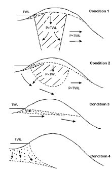
In some cases leakage from reservoirs can be a potential source of trouble. When a dam impounds a body of water behind it, the rocks forming the floor of the reservoir are subjected to considerable hydraulic pressure. The water under hydraulic head will find its way through interconnected joints, bedding planes and porous rocks. If these joints and bedding planes dips towards the adjoining valleys this leakage from the reservoir will be considerable. Piezometric Conditions The water from the reservoir may seep through the flanks of the reservoir and the river bed and may recharge the subsurface water regime of the area. However, it is not always true that the reservoir water will recharge the subsurface water of the region, the flow in some conditions may be from the subsurface water towards the reservoir. For this the factors which influence the water leakage from the reservoir are; (i) Piezometric conditions in the reservoir’s floor & flanks and (ii) Natural permeability of the floor and flanks Subsurface Water Conditions Existing on the Flanks of a Reservoir Knill (1971) explained that four subsurface water conditions exist on the flanks of the reservoir these are;
The subsurface water has a potential to change the engineering properties of the rocks and soils. Thus, the bearing capacity of soils may be considerably reduced because of the subsurface water. The strength of the rocks is also affected when they are saturated with water. Some of the soils possess expensive nature and when these soils are subjected to change in moisture level they may expand thus any structure constructed over these soils may be damaged because of the uplift pressures. Similarly, during the seasonal fluctuation of subsurface water the soils may be unsaturated and thus the soils may shrink which may result into settlement of the structures constructed over them. The deformation of the expensive soils, as foundation material, may result into uneven settlement or upheaval of the structures, this may result into cracks in the walls and the floor of the structure, however in extreme condition the entire structure can fail. The role of subsurface water in pavement design has an important consideration. The fluctuations in subsurface water conditions are responsible in changing the properties of the subgrade. Repeated wetting and drying of the subgrade may considerably reduce the bearing capacity of the soil. Generally, it happens that the wet soil along the shoulders dry faster than the crown area of the pavement this results in variation of the strength of the subgrade material. Such variations in the strength property of the subgrade material results into longitudinal cracks in the pavement. Engineering Significance of Subsurface Water in stability conditions of slopes The important factors which influence the stability of the rock or soil slopes are; slope angle, dip of the failure plane or plunge of the line of intersection of two wedge forming planes, shear strength parameters, cohesion and angle of internal friction and finally the water saturation condition. For the stability condition either of the above mentioned factors may have comparatively high or low influence. Some of the factors may be responsible in inducing the forces for sliding where as, the others may contributes in providing the resistance to the sliding. The net result of these factors will defines whether the slope is going to slide, under the given conditions, or it will be stable. The relationship of the factors responsible for inducing sliding and the factors responsible to provide resistance to the sliding is defined by the limit equilibrium. Factor of safety can be defined as the ratio of the total forces available to resist sliding to the total forces available to induce sliding. If the factor of safety is less than unity, it implies that the resistive forces are less than that of the forces, which induce sliding. Thus, for the condition when the FOS is less than 1.0 the slope may fail, provided it is subjected to a triggering factor, natural or man made. The factor of safety of a potential unstable slope may be improved by providing several methods such as, safe slope design by altering the geometry of the slope, reinforcement by providing rock bolts, retaining structures, shotcreating etc. The role of subsurface water in stability condition of a slope is very crucial. As it has a potential to saturate the soil mass and thus increases the overall weight of the soil mass. |
Article published on Nov. 23rd 2006 Back to main page
This increase in weight of the soil mass is a negative factor as far as the stability of the slope is concerned. The presence of subsurface water will reduce the shear strength of the soil mass and also it may generate the pore water pressure which ultimately affects the stability condition of the slope. The subsurface water in the discontinuity planes of the rock mass develops an uplift water force thus reducing the strength of the rock mass. The water not only reduces the shear strength of the rock mass but it also works as a lubricant and facilitates the process of sliding along possible failure surfaces. In majority of the cases the subsurface water is the most important parameter, which affects the stability condition of the slopes. For this reason only most of the slope failures takes place during rainy season. Protective measures to control adverse effects of subsurface conditions As the subsurface water has a most crucial effect in reducing the stability condition of the slopes, therefore all care must be taken to control the adverse effects of the subsurface water. This may be done by following two approaches, one as a preventive measure in which, efforts are made to reduce the excess inflow of the water into the slope and the second approach is the curative measures. Slope De-Pressurization Water pressure decreases the stability of a slope, it follows that reduction of this water pressure will increase the stability of the slope. The following points are important for slope de-pressurization;
Surface Drains Surface drains are designed to collect run off before it reaches the area immediately behind the crest of the slope. These drains are important because they are constructed in the area where tension crack occur. Therefore, these drains must be cleaned from silt or clay or any blockage material, so that there is no pondage of water, which may enter into the tension crack which ultimately recharge the subsurface water. 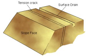
Fig. 2 Surface drain on upper slope surface to check the infiltration of surface water through tension crack. Upper Slope Surface The upper slope surface, immediately behind the crest, is an area of considerable potential danger since water, which is allowed to pond in this area will certainly finds its way into the slope through open tension cracks and fissures. Grading of this surface and the removal of piles of waste rock or overburden which could cause damming will enhance run-off of any collected water. Open Tension Crack Open tension cracks are very dangerous in areas liable to higher intensity rainfall since the water forces generated by a water filled tension crack can be very high and can induce very sudden slope failures. In addition to diverting surface water away from open tension cracks, it is advisable to prevent water from entering the cracks, by sealing them with a flexible impermeable material such as clay. When the crack is more than few inches wide it should be filled with gravel or waste rock before the flexible seal is placed. Under no circumstances the tension crack be filled with concrete or grout since this would result in the creation of an impermeable dam, which cause the build up of high water pressure in the slope. Horizontal and collection Drains Horizontal drain holes drilled into the slope face can be very effective in reducing water pressure generated by the subsurface water near the base of the suspected tension crack or along a potential failure plane. Water which is drained out of the rock mass should be lead away in collection drains otherwise this water will simply find its way into the next bench and the problem will transfer form one level to the lower level. 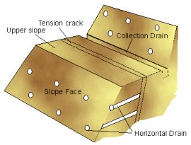
Fig. 3 Horizontal drains through the slope face to intercept the subsurface water and to guide through the surface collection drains. Vertical Drainage Wells Vertical drainage wells drilled from the slope surface and fitted with down hole pump can be effective in slope drainage and de-pressurization. Drainage Galleries Drainage galleries with or without fans of radial holes are the most effective means of sub-surface drainage. Effect of subsurface water chemistry on engineering structures In engineering structures subsurface water is an agent of solution by virtue of its acidity and in soils it is an agent of piping by virtue of its dissolved solids. Carbonic acid attacks concrete structures by stripping of Ca++ and Mg++, which are then carried off in solution and sulfuric acid attacks concrete by driving of the Ca++. This phenomena is common for all concrete foundation structures. Moreover, The corrosiveness of subsurface water affects the weathering intensity of the rocks, buried pipes and structures. Total sulphate content of 300 ppm (75 milligram/litre) in subsurface water have been classified as potentially aggressive. Sulfate when present in large amount, is aggressive to concrete, metallic structures, like rock bolts, steel used as reinforcement etc. Hydrogen sulfide may result sulfuric acids by the action of oxygen and water. The sulfuric acid will facilitates the weathering process of the native foundation rock causing decrease in strength. The foundations in soils are not susceptible to acidity of the subsurface water. The effect of subsurface water chemistry is on the piping effect. The dispersive nature of soils depends on the ‘exchangeable sodium percentage’(ESP), however values of ESP causes serious piping when the ESP value of the foundation soils is greater than 15 and the subsurface water has a ESP value lower than 0.5. The ESP can be determined as; ESP = Na/ (Na+K+Ca+Mg) *100 …….1.0 Corrosivity of Subsurface Water The coexistence of sulphate and chloride ions in subsurface water causes deterioration of reinforcement (concrete or other steel structures). The corrosivity of the subsurface water can be determined from the corrosivity ratio coefficient, CR (Mahadevaswamy, 2002). In corrosive subsurface water conditions, while doing excavations, a proper precaution has to be taken to reduce the effect of corrosion, especially in permanent excavations. According to Mahadevaswamy (2002), the value of the corrosivity coefficient can be determined from the following expression; Thus if the CR value is >1 the subsurface water is corrosive. Therefore, it is desirable to determine the corrosivity ratio coefficient, CR for the safety of the concrete and other reinforcements, particularly when the foundations are laid down in the zone of subsurface water. Control of Subsurface Water A variety of methods exist for controlling subsurface water. Choosing the method or combination of methods to use depends on the type of engineering work involved, site conditions and the purpose for controlling the water. Control methods can be reasonably grouped into four categories; (i) barriers, (ii) liners, (iii) wells and (iv) drains. Barriers are generally employed to reduce both quality and velocity of subsurface water ; liners are used to prevent the movement of subsurface water; drains reduces the quantity of water and direct its movement. Dewatering, the elimination of subsurface water, is accomplished through the use of wells. Each method has advantages and disadvantages that require careful attention when choosing the control method or methods for a specific project. Barriers and Liners Sheet pile cutoff walls, impervious cutoff trenches and grouted or injected cutoff curtains are common types of barriers. Barriers are often part of structures. For example, earthern dams may incorporate a cutoff wall or grout curtain in their foundation to reduce the amount and speed of water flowing under the structure. The type of barrier to use at a site is dictated as much by subsurface conditions as by the type of structure involved. For instance, coarse grained material and stratified soil with alternating layers of pervious and impervious material are ideal for for use use of sheet pile barriers. Conditions affecting the ability to excavate a trench to the necessary depth and maintain its shape will determine whether placement of impervious soil barriers are approximate. Liners are used to prevent the seepage. This may involve preventing loss of water retained in a canal or impoundment or keeping water out of an area such as a waste disposal site to prevent migration of contaminations. Bentonite and related clays are often favored as liners to prevent water from reaching isolated waste. Some caution in relying on this method, however, should be exercised due to questions concerned their long term efficiency. Drains and Wells Effective drains depends on the relative permeability of the drain materials and the surrounding materials. Besides the selection of the drain material must be such that it must retain the migration of the fine particles from the surrounding. Such type of drains are used for structures where the subsurface water has to be drained out from the likely affected area and the uplift water pressures developed by the subsurface water has to be checked. The relative sizing of drain materials is critical to proper operation. It must have a sufficiently greater permeability than the soil it is protecting in order to intercept the subsurface flow. At the same time, it must not permit excessive passage of the smaller particles in the adjacent materials to avoid piping of the soil or clogging of the drain. Cedegren(1977) notes that the following design criteria are commonly used to address this problem; D is equal to the diameter of particles at the percentile of gradation curve indicated by the subscript for the soil and filter medium. This relationship was originally developed for use with graded aggregate. The growing use of geotechnical fabrics or filter cloth has modified this problem. Sizing aggregate is less critical for a drain where a filter cloth is included to prevent smaller particles in the soil from migration into the drain. Fabrics may be ordered with different effective opening size (EOS) to permit the right fabric to be chosen for the gradation of a particular soil. Drains are basically either blanket or interceptor types. Blanket drains are a narrow layer of drainage material placed between the sources of subsurface flow and the area or structure being protected. Interceptor drains are some type of excavated filled with drainage material placed to catch and redirect the flow of subsurface water before it reaches the area of concern. The effectiveness of a blanket drain depends on its ability to carry away water from the site. Different designs for a particular site may have differing capacities. The drainage capacity of a blanket drain can be estimated by eq.1.4 Q = k.i.A …….1.4 Where; ‘Q’ is the discharge, ‘k’ is the coefficient of the permeability, ‘i’ is the average gradient in flow direction and ‘A’ is the cross sectional area of blanket. Common types of wells used to dewater a site are; sumps, well points, pumping wells, relief wells and horizontal drains. A sump is merely a collection trench, or hole, deeper than the area being protected from subsurface water. As the water collects, it is pumped away from the area, effectively drawing down the water table. Well points accomplish the same purpose by being drilled to a shallow depth and attached to a suction pump to draw out the water. Pumping wells are necessary to achieve dewatering to a greater depth owing to the limitations of suction pumping used with well points. Pumping wells are drilled and equipped in a manner nearly identical to a well being developed as a water source. Relief wells are employed to decrease water in a confined aquifer. The artesian pressure forces the water upward through the relief well. The relief well is, in essence, a vertical interceptor drain. It is often used for dewatering during construction and to relieve uplift pressure on foundations. Horizontal wells depends on gravity to move water through them. These wells are effective in maintaining cut slope stability and in stabilizing landslides. The geology and topography of a location will dictate the most desirable location to intercept the subsurface water before it reaches an area of possible instability. Attention should be paid to lateral as well as vertical changes in lithology when analyzing a site. By knowing these factors, spacing of wells and their length can achieve a better result than equal spacing and predetermined lengths. References Bell,F.G, 1980 “Engineering Geology and Geotechnics”, Newnes-Butterworths, London, UK. Getinet Asfaw, 2005 ‘’Engineering Geological study on Rib dam project, South Gonder (North-Western Ethiopia)’’, unpublished M.Sc Thesis, Department of Earth Sciences, Addis Ababa University, Ethiopia. Hoek, E and Bray, J.W., 1997, “Rock Slope Engineering”, E&FN Spon and Imprint of Chapman and Hall, 2-6 Boundary Row, London SEI 811 N, UK. Johnson, R.B and Degraff, J.V, 1991 “Principles of Engineering Geology”, John Wiley and Sons, New York.. Mahadevaswamy, G.M, 2002 ‘’ Hydrogeologic appraisal using conventional and remote sensing methodology of Lokapavani Microwater shed, Mandya District, Karnataka, India’’, Unpublished Ph.D Thesis, University of Mysore Yonas Bekele, 2004 ‘’Legadembi gold open pit mine slope stability and underground mine geotechnical study’’, unpublished M.Sc Thesis, Department of Earth Sciences, Addis Ababa University, Ethiopia.
|